Provides excitation current for up to 4 model 229 soil-water sensors


Overview
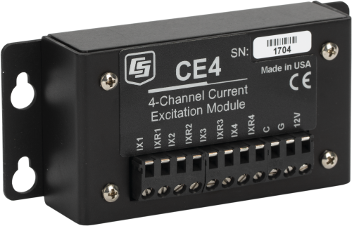
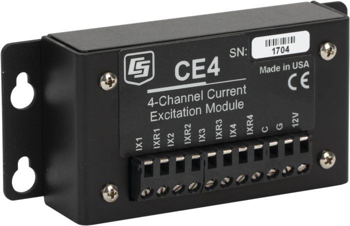
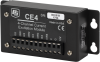
The CE4 is a current-excitation module that applies a constant current to the heating element of up to four 229 Heat Dissipation Water Matric Potential Sensors. A current-excitation module is required when you use 229 sensors to measure soil water matric potential.
Read MoreBenefits and Features
- Provides excitation current for up to four 229 sensors
- Allows up to four AM16/32-series multiplexers to be connected, which significantly expands the system's capacity
- Compatible with most Campbell Scientific data loggers
Images
CAD Files:
Detailed Description
A CE4 current excitation module can provide a constant current to the heating element of the 229. The CE4 sources current for up to four 229s. The module requires a 12 Vdc power source. The number of 229 sensors measured by one data logger can be increased by connecting a CE4 to one or more AM16/32-series multiplexers. Up to four multiplexers can be connected to the CE4.
Note: The CE4 module switches currents that are greater than 30 mA, which degrades the contact surfaces of the mechanical relays. Therefore, the multiplexer channels to which the CE4 have been connected may become unsuitable for other applications. (Refer to the multiplexer manual for more information.)
Compatibility
Note: The following shows notable compatibility information. It is not a comprehensive list of all compatible or incompatible products.
Data Loggers
| Product | Compatible | Note |
|---|---|---|
| 21X (retired) | ||
| CR10 (retired) | ||
| CR1000 (retired) | ||
| CR1000X (retired) | ||
| CR1000Xe | ||
| CR10X (retired) | ||
| CR200X (retired) | ||
| CR206X (retired) | ||
| CR211X (retired) | ||
| CR216X (retired) | ||
| CR23X (retired) | ||
| CR295X (retired) | ||
| CR300 (retired) | ||
| CR3000 (retired) | ||
| CR310 | ||
| CR350 | ||
| CR500 (retired) | ||
| CR5000 (retired) | ||
| CR510 (retired) | ||
| CR6 | ||
| CR800 (retired) | ||
| CR850 (retired) | ||
| CR9000 (retired) | ||
| CR9000X (retired) |
Additional Compatibility Information
Data Logger Considerations
The CABLE3CBL can be used to connect the CE4 to the data logger (see Ordering Info).
Power Considerations
The CE4 requires 12 Vdc power. A data logger control port is typically used to activate the module. When the control signal is received, all 4 channels output a 50 mA source current to the connected loads (typically 229 probes). When the control signal is dropped to 0 Vdc, output from the module ceases.
When active, the current required from the 12 V supply is approximately the following:
25 mA + (50 mA)(the number of 229 sensors connected to the CE4 outputs).
Multiplexers
The CE4 can source current for four probes directly. In applications that require more sensors, the output(s) of the CE4 can be connected to as many as four AM16/32B multiplexers, greatly expanding system capacity.
When using multiplexers, the user should be aware that switching currents of greater than 30 mA will degrade the contact surfaces of the mechanical relays. This will adversely affect the suitability of these relays to multiplex low voltage signals. Although a relay used in this manner no longer qualifies for low voltage measurements, it continues to be useful for switching currents in excess of 30 mA. Therefore the user is advised to record which multiplexer channels are used to multiplex the 50 mA excitation for the 229-L probes in order to avoid using those channels for low voltage measurements in future applications.
Enclosure Considerations
The CE4 requires a desiccated, non-condensing environment; a Campbell Scientific enclosure is recommended. The CE4's case has mounting flanges for attachment to the 1"-on-center hole grid of Campbell Scientific enclosures. Grommets and screws are provided to attach the flanges to the backplate of our enclosures.
Specifications
| Output | 50 mA ±0.25 mA (regulated) |
| Output Channels | 4 |
| Power | 12 Vdc source required |
| Active Current Drain | 25 mA + (50 mA) x (number of 229s connected to the CE4) |
| Dimensions | 11.5 x 5.4 x 2.7 cm (4.5 x 2.1 x 1.1 in.) |
| Weight | 131 g (4.6 oz) |
Documents
Frequently Asked Questions
Number of FAQs related to CE4: 3
Expand AllCollapse All
-
The CE4 and CE8 have CMOS circuitry controlled by a 0 to 5 Vdc analog signal provided by a data logger control port.
-
No. Typically a PRT will experience self-heating if more than 1 mA of current excitation is applied, while the CE4 or CE8 output is 50 mA.
-
While this could be done for a maximum resistance of 50 ohms in the ±2500 mV range and 100 ohms in the ±5000 mV range, it is not the best way to determine resistance. The preferred method for measuring an unknown resistance is to use data logger excitation channels. Current excitation channels can be used with a CR3000. Analog excitation channels with half-bridge or full-bridge circuitry can be used for other data loggers. See the specific data logger’s manual for further details
Listed Under
Privacy Policy Update
We've updated our privacy policy. Learn More
Cookie Consent
Update your cookie preferences. Update Cookie Preferences