
Overview
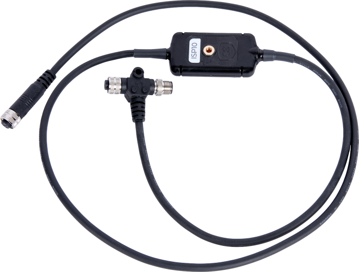
The ISP10 is a surge protection device for Modbus RTU sensors. The ISP10 provides protection that meets the IEC 61000-4-5, level 4 (4 kV, 2000 A) surge protection standard. It incorporates a T-junction that allows a sensor to be connected inline. The five-pin M12 connectors are configured to match the SunSentry system's trunk-line cable pinout, which is compatible with the RS485CBL 24 AWG RS-485 Cable with M12 Five-Pin Connector.
The ISP10 ties the sensor connector to earth ground via cable shielding. The trunk line cable shield passes through the T-junction untouched by the ISP10 and should be terminated separately at the main meteorological (met) enclosure.
Read MoreBenefits and Features
- Inexpensive surge protection for any digital sensor
- Surge protection to IEC 61000-4-5, level 4 (4 kV, 2000 A) standard
- Sensor cable shield termination to ground while passing trunk-line shield to a single point
- Common shorting of signal lines to ground after a powerful surge event, enabling easy line troubleshooting and repair
- Easy installation or replacement
Images
Similar Products
Detailed Description
The ISP10 uses a standard A-coded, five-pin M12 connector with shield termination via the coupling nut. The T-junction uses one plug M12 connector (for the incoming trunk line) and two socket M12 connectors (one for the continuing trunk line and one for the sensor port). Various pin adapters are available to change the pinouts of common sensors for compatibility with the ISP10 and the standard Campbell Scientific pinout.
One ISP10 can be connected directly to another ISP10 side by side without cabling when sensors are close to one another. Alternatively, the RS485CBL-Xm-M can be used to daisy-chain one sensor or ISP10 to another.
A hole in the middle of the ISP10 is used for grounding and mounting with the included #10 screw. Mount the ISP10 to an earth-grounded, conductive part for proper surge protection.
The ISP10 is shipped with the following items:
- #17 high-speed steel drill bit for pilot hole required for the self-tapping screw
- Self-tapping screw (#10-32 x 1 410SS hex washer head thread cutting screw)
- 5 cc packet protective oxide-inhibitor grease
Pinout Description for ISP10
| M12 Pin Number | Function |
|---|---|
| 1 | V+ |
| 2 | Signal |
| 3 | Signal Ground |
| 4 | V Ground |
| 5 |
Signal |
| Coupling Nut |
Cable Shield |
Compatibility
Note: The following shows notable compatibility information. It is not a comprehensive list of all compatible or incompatible products.
Sensors
| Product | Compatible | Note |
|---|---|---|
| ClimaVue 40 | ||
| CS241DM G2 | ||
| DustVue 10 | ||
| DustVue 20 | ||
| SR30 |
Additional Compatibility Information
The following sensors can be adapted for use with the RS485CBL and SunSentry RS-485 network topology:
- CS241DM (with the 44340 RS485CBL Adapter for SunSentry Used with CS241DM G2 Temperature Sensor)
- Hukseflux Modbus RTU sensors
- EKO Modbuse RTU sensors (with the 44338 RS485CBL Adapter for SunSentry Used with Digital EKO Pyranometer)
- Atonometrics Modbus RTU sensors (with the 44339 RS485CBL Adapter for SunSentry Used with Atonometrics Sensor [RC22 PV Reference Cell])
Specifications
| Operating Temperature Range | -40° to +85°C |
| Maximum DC Operating Voltage | 27.5 Vdc |
| Maximum Load Current | 4 A (@ 25°C) |
| Surge Protection |
IEC 61000-4-5 Surge Standard (4 kV, 2000 A) |
| Maximum Line Current | 4 A |
| Maximum Data Rate | 115,200 baud |
| Connection to Network | M12, five-pin, A-coded plug and socket connectors |
| Cable Configuration | Five-wire cable with shield - 1 data channel (1 twisted pair + G for 100 ohm impedance) + power (pwr + gnd) + shield |
| Mounting and Grounding | Inline with cable, center mounting hole is connected to the earth ground. Self-tapping screw provided to secure the body to a grounded surface. |
| Enclosure Rating | IP67 |
| Number of Surge Events | 10 maximum (replacement frequency based upon frequency of lighting in the region) |
| Environmental Standards | RoHS 3 Directive 2015/863 |
| Total Length | 1.45 m (57.0 in.) |
| Cable Length to Sensor | 0.95 m (37.0 in.) |
| Cable Length to Tee | 0.45 m (17.0 in.) |
| Weight | 152 g (5.4 oz) |
Documents
Listed Under
Privacy Policy Update
We've updated our privacy policy. Learn More
Cookie Consent
Update your cookie preferences. Update Cookie Preferences