This product is not available for new orders.
| Services Available | |
|---|---|
| Repair | No |
| Calibration | No |
| Free Support | Yes |
Overview
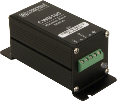
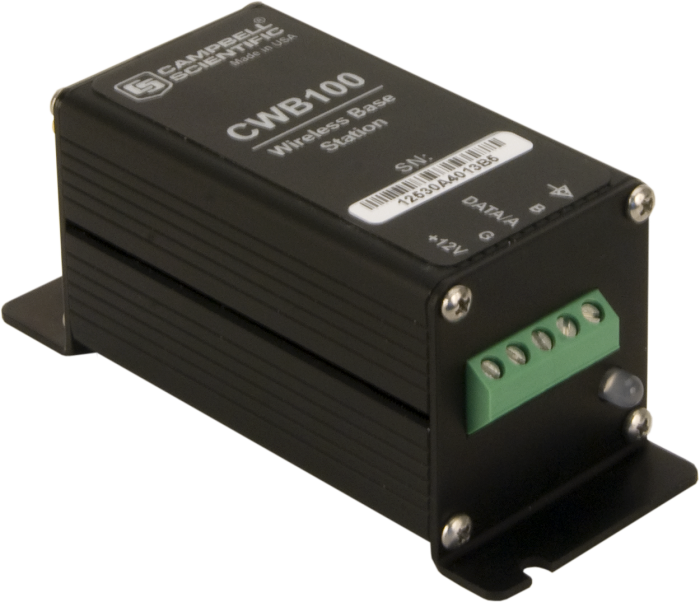
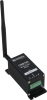
The CWB100 is the master radio you use in a Campbell Scientific wireless-sensor network. It polls and stores data from up to 50 wireless sensors, and then passes that data to a data logger. Its internal radio has a 902 to 918 MHz frequency range, which is used in the US and Canada.
Read MoreBenefits and Features
- Internal frequency-hopping, spread-spectrum radio provides longer range and less interference
- Polls and stores data from up to 50 wireless sensors
- Configurable to fit your application
Images

Detailed Description
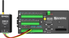
The CWB100 base station is configured using an A205 CWS to PC Interface and Campbell Scientific’s Wireless Sensor Planner, Network Planner or Device Configuration Utility software. The data logger is programmed to interface with the CWB100 and determine a polling interval. After the polling interval has been received, the base station uses that information to poll the sensors prior to being polled by the data logger.
Why Wireless?
There are situations when it is desirable to make measurements in locations where the use of cabled sensors is problematic. Protecting cables by running them through conduit or burying them in trenches is time consuming, labor intensive, and sometimes not possible. Local fire codes may preclude the use of certain types of sensor cabling inside of buildings. In some applications measurements need to be made at distances where long cables decrease the quality of the measurement or are too expensive. There are also times when it is important to increase the number of measurements being made but the data logger does not have enough available channels left for attaching additional sensor cables.
This product will be discontinued as of 10 April 2017. Please review the CWS-Series and CWB-Series Discontinuation Notice for further details.
Compatibility
Note: The following shows notable compatibility information. It is not a comprehensive list of all compatible or incompatible products.
Data Loggers
| Product | Compatible | Note |
|---|---|---|
| CR1000 (retired) | The CR1000 datalogger must have data logger OS version 21 or higher. | |
| CR200X (retired) | ||
| CR206X (retired) | ||
| CR211X (retired) | ||
| CR216X (retired) | ||
| CR295X (retired) | ||
| CR3000 (retired) | The CR3000 datalogger must have data logger OS version 21 or higher. | |
| CR6 | The CR6 datalogger must have data logger OS version 4.0 or higher. | |
| CR800 (retired) | The CR800 datalogger must have data logger OS version 21 or higher. | |
| CR850 (retired) | The CR850 datalogger must have data logger OS version 21 or higher. | |
| CR9000X (retired) |
Additional Compatibility Information
Data Logger Considerations
The data logger is programmed to interface with the CWB100 and determine a polling interval. The sensors make their measurements as they are polled. The base station polls all sensors and stores the collected data early enough that it can transfer the data as soon as the data logger requests it. This minimizes the amount of time the data logger needs to wait for a response from the network through the CWB100 base station.
At the start of each polling interval, the data logger polls the base station, and sensor values are transferred to the data logger for storage. This method of data transfer from the sensors to the data logger provides the fastest and lowest power method available.
Specifications
| Power Source | Data logger |
| Voltage | 4.5 to 22 Vdc |
| Operating Temperature Range | -25° to +50°C |
| Operating Relative Humidity Range | 0 to 100% |
| Standby Typical Current Drain | < 1 mA (@ 12 Vdc) |
| Receive Typical Current Drain | 10 mA (@ 12 Vdc) |
| Transmit Typical Current Drain | 20 mA (@ 12 Vdc) |
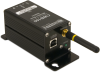
| Communication | Serial protocol or USB |
| Terminal Block Connector | Bi-directional serial data logger connection |
| USB Port | Computer connection for configuration |
| Antenna Connector | RPSMA antenna connection |
| Memory Capacity | Can store data table for up to 50 wireless sensors. |
| Dimensions | 10.8 x 4.4 x 4.4 cm (4.25 x 1.75 x 1.75 in.) |
| Weight | 140 g (5 oz) |
Internal 25 mW FHSS Radio |
|
| Frequency | 902 to 918 MHz |
| Where Used | US and Canada |
| FHSS Channel | 50 |
| Transmitter Power Output | 25 mW (+14 dBm) |
| Receiver Sensitivity | -110 dBm (0.1% frame error rate) |
| Standby Typical Current Drain | 3 μA |
| Receive Typical Current Drain | 18 mA (full run) |
| Transmit Typical Current Drain | 45 mA |
| Average Operating Current | 15 μA (with 1-second access time) |
| Quality of Service Management | RSSI |
| Additional Features | GFSK modulation, data interleaving, forward error correction, data scrambling, RSSI reporting |
Documents
Technical Papers
Miscellaneous


Downloads
To find previously purchased software downloads, log in to the website using the same account the software was purchased under. Navigate to the account's Purchased Software section.
CWB100 USB Driver () 01-01-2014
Windows USB drivers for the CWB100 are installed via the Device Configuration Utililty. In the Device Configuration Utility, click on the link "install the device driver for the CWB100" in the main body of text for the CWB100.
Note: Driver must be installed before connecting the CWB100 to your computer.
Wireless Sensor Planner v.1.7 (30.5 MB) 08-08-2013
The Wireless Sensor Planner is a tool for use with Campbell Scientific wireless sensors. It assists in designing and configuring wireless sensor networks.
Frequently Asked Questions
Number of FAQs related to CWB100: 3
Expand AllCollapse All
-
The SDI-38 communications protocol between the data logger and CWB100 is proprietary to Campbell Scientific. Contact support@campbellsci.com for more information.
-
Because the devices and the radios use the same frequency bands, there will be interference. Factors affecting the amount of interference include the distances between the communications radio and the CWS radios, and the distances between the CWS base and the sensors. Also, the amount of interference is affected by whether the communications radio is set up as a master.
-
Only one CWB100 can be connected to each odd channel control port. For the CR800 and CR850, this relates to two total units—one on C1 and one on C3. On the CR1000 and CR3000, this amounts to four total units.
Putting more than one CWB100 on a data logger will NOT speed up sensor data collection. Only one CWB100 should be accessed at any given time, or the devices will interfere with each other. If multiple CWB100 devices are connected to a single data logger, the data collection schedules for the CWB100 devices should be staggered. Sufficient time should be built in to allow each base unit to collect data from all of the remote sensors associated with it and to allow for any needed retries.
Articles and Press Releases
Newsletter Articles
Privacy Policy Update
We've updated our privacy policy. Learn More
Cookie Consent
Update your cookie preferences. Update Cookie Preferences