
Use as part of open-path eddy-covariance systems or as a stand-alone IRGA


Overview
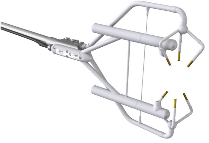
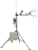
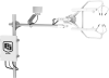
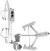
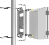
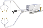
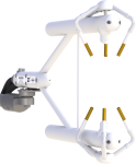
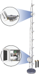
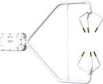
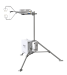
Campbell Scientific’s EC150 is an open-path analyzer specifically designed for eddy-covariance carbon and water flux measurements. As a stand-alone analyzer, it simultaneously measures absolute carbon-dioxide and water-vapor densities, air temperature, and barometric pressure. With the optional CSAT3A sonic anemometer head, three-dimensional wind speed and sonic air temperature are measured.
Read MoreBenefits and Features
- New conformal coating helps protect sonic transducers in corrosive environments
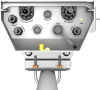
- Unique optical configuration gives a slim aerodynamic shape with minimal wind distortion
- Analyzer and sonic anemometer measurements are synchronized by a common set of electronics
- Maximum output rate of 60 Hz with 20 Hz bandwidth
- Low power consumption; suitable for solar power applications
- Low noise
- Measurements are temperature compensated without active heat control
- Angled windows to shed water and are tolerant to window contamination
- Field rugged
- Field serviceable
- Factory calibrated over wide range of CO2, H2O, pressure, and temperature in all combinations encountered in practice
- Extensive set of diagnostic parameters
- Fully compatible with Campbell Scientific dataloggers; field setup, configuration, and field zero and span can be accomplished directly from the datalogger
- Speed of sound determined from three acoustic paths; corrected for crosswind effects
- Innovative signal processing and transducer wicks considerably improve performance of the anemometer during precipitation events
Images


Similar Products
Detailed Description
The CSAT3A has the following outputs:
- Ux (m/s)*
- Uy (m/s)*
- Uz (m/s)*
- Sonic Temperature (°C)*
- Sonic Diagnostic*
The EC150 has the following outputs:
- CO2 Density (mg/m3)
- H2O Density (g/m3)
- Gas Analyzer Diagnostic
- Ambient Temperature (°C)
- Atmospheric Pressure (kPa)
- CO2 Signal Strength
- H2O Signal Strength
- Source Temperature (°C)
*The first five outputs require the CSAT3A Sonic Anemometer Head.
EasyFlux® DL is a free CRBasic program for Campbell open-path eddy-covariance systems that is available in the Downloads section. To learn more about EasyFlux® DL, visit the software product's web page.
Compatibility
Specifications
| Operating Temperature Range | -30° to +50°C |
| Calibrated Pressure Range | 70 to 106 kPa |
| Input Voltage Range | 10 to 16 Vdc |
| Power | 5 W (steady state and power up) at 25⁰C |
| Measurement Rate | 60 Hz |
| Output Bandwidth | 5, 10, 12.5, or 20 Hz (user-programmable) |
| Output Options | SDM, RS-485, USB, analog (CO2 and H2O only) |
| Auxiliary Inputs | Air temperature and pressure |
| Gas Analyzer/Sonic Volume Separation | 5.0 cm (2.0 in.) |
| Warranty | 3 years or 17,500 hours of operation (whichever comes first) |
| Cable Length | 3 m (10 ft) from EC150 and CSAT3A to EC100 |
| Weight |
|
Gas Analyzer |
|
| Path Length |
15.37 cm (6.05 in.)
A temperature of 20°C and pressure of 101.325 kPa was used to convert mass density to concentration. |
Gas Analyzer - CO2 Performance |
|
| -NOTE- | A temperature of 20°C and pressure of 101.325 kPa was used to convert mass density to concentration. |
| Accuracy |
|
| Precision RMS (maximum) |
0.2 mg/m3 (0.15 µmol/mol)
Nominal conditions for precision verification test: 25°C, 86 kPa, 400 μmol/mol CO2, 12°C dewpoint, and 20 Hz bandwidth. |
| Calibrated Range | 0 to 1,000 μmol/mol (0 to 3,000 µmol/mole available upon request.) |
| Zero Drift with Temperature (maximum) | ±0.55 mg/m3/°C (±0.3 μmol/mol/°C) |
| Gain Drift with Temperature (maximum) | ±0.1% of reading/°C |
| Cross Sensitivity (maximum) | ±1.1 x 10⁻⁴ mol CO2 /mol H2O |
Gas Analyzer - H2O Performance |
|
| -NOTE- | A temperature of 20°C and pressure of 101.325 kPa was used to convert mass density to concentration. |
| Accuracy |
|
| Precision RMS (maximum) |
0.004 g/m3 mmol/mol (0.006 mmol/mol) Nominal conditions for precision verification test: 25°C, 86 kPa, 400 μmol/mol CO2, 12°C dewpoint, and 20 Hz bandwidth. |
| Calibrated Range | 0 to 72 mmol/mol (38°C dewpoint) |
| Zero Drift with Temperature (maximum) | ±0.037 g/m3/°C (±0.05 mmol/mol/°C) |
| Gain Drift with Temperature (maximum) | ±0.3% of reading/°C |
| Cross Sensitivity (maximum) | ±0.1 mol H2O/mol CO2 |
Sonic Anemometer - Accuracy |
|
| Offset Error |
|
| Gain Error |
|
| Measurement Precision RMS |
|
| Speed of Sound | Determined from 3 acoustic paths (corrected for crosswind effects) |
| Rain | Innovative ultrasonic signal processing and user-installable wicks considerably improve the performance of the anemometer under all rain events. |
Ambient Temperature |
|
| Manufacturer | BetaTherm 100K6A1IA |
| Total Accuracy | ±0.15°C (-30°C to +50°C) |
Documents
Manuals
Technical Papers
Miscellaneous
- Improved Flux Measurements from Campbell Scientific Open-Path Gas Analyzers: Utilizing Sonic Temperature to Account for Spectroscopic Effects on CO2 Density
- Influence of Open-path Gas Analyzer Flow Distortion on Ultrasonic Wind Measurements
- Using Molecular Sieve to Zero Infrared Gas Analyzers for Eddy Covariance or Atmospheric Profile Measurements
- IRGASON and EC150 Source and Detector Cover Updates


Downloads
To find previously purchased software downloads, log in to the website using the same account the software was purchased under. Navigate to the account's Purchased Software section.
EasyFlux DL for CR6OP v.2.02 (99.2 KB) 10-31-2025
CR6 datalogger program for Campbell open-path eddy-covariance systems.
ECMon v.1.6 (10.7 MB) 03-29-2016
EC100-Series Support Software.
EC100 OS v.8.02 (560 KB) 10-14-2019
EC100 Operating System.
Watch the Video Tutorial: Updating the EC100 Operating System.
Device Configuration Utility v.2.34 (49.5 MB) 06-03-2026
A software utility used to download operating systems and set up Campbell Scientific hardware. Also will update PakBus Graph and the Network Planner if they have been installed previously by another Campbell Scientific software package.
Supported Operating Systems:
Windows 11 or 10 (Both 32 and 64 bit)
CSAT3H Heater Controller v.14.2 (46 KB) 02-02-2021
The CSAT3H Heater Controller ships with this encrypted program. This program is for the unlikely event that the program needs to be re-installed or updated to a newer version. Please contact Campbell Scientific if you have questions about the program or would like the algorithm modified for a specific application.
EasyFlux DL for CR1000XOP v.2.02 (99.2 KB) 10-31-2025
CR1000X datalogger program for Campbell open-path eddy-covariance systems.
Frequently Asked Questions
Number of FAQs related to EC150: 21
Expand AllCollapse All
-
Yes. A fine-wire thermocouple, such as a FW05, can be used.
-
The EC150 and IRGASON™ gas analyzer windows are polished, slanted at an angle, and coated with a hydrophobic material to prevent water from collecting on their surfaces. Wicks may also be used on the windows to promote capillary action and move water away from the window edges. Also, heaters in the snouts may be turned on to help minimize data loss because of precipitation and condensation events.
-
Selecting which barometer to use is the choice of the user. There is a direct correlation between the accuracy level of the barometer and its cost.
- The basic barometer has an accuracy of ±1.5 kPa between 0° and 50°C. Below 0°, the error increases linearly to ±3.7 kPa at -30°C.
- The enhanced barometer offers an accuracy of ±0.15 kPa (-30° to +50°C).
When choosing a barometer, consider the effect of pressure accuracy on flux calculations. For sensible heat flux, the barometric pressure is used to calculate the density of air, which directly scales the sensible heat flux. Therefore, if the barometric pressure measurement is off by 1%, then the sensible heat flux will be off by 1%.
For CO2 flux, the EC150 and IRGASON™ report CO2 as density. Thus, the barometric pressure is not used to directly calculate the flux. However, error in pressure measurements could cause an error in CO2 flux resulting from a CO2 span. During the span procedure, the user enters the “true CO2 value” as a CO2 concentration, which is later converted to density using the barometric pressure. Consequently, the error in CO2 measurements is directly proportional to the error in the barometric pressure measurement.
-
The factory calibration accounts for CO2 and H2O signal strengths down to 0.7. Therefore, to ensure quality data, windows should be cleaned before signal strengths drop below 0.7.
-
The power requirement for the IRGASON™ or EC150 with CSAT3A is 5 W at room temperature regardless of whether it is powering up or under steady-state operation. At extreme cold or hot temperatures, the power requirement reaches 6 W.
-
The barometer and temperature sensor are needed because the IRGASON™ and EC150 have been calibrated at the factory over a range of temperatures (-30° to +50°C) and barometric pressures (70 to 106 kPa).
-
EdiRe (University of Edinburgh) and MATLAB (MathWorks) are two of the products eddy-covariance customers have used to post-process their data. Others are also available. (For more information, review the EdiRe technical paper titled “EdiRe Software for Micrometeorological Applications.)
Campbell Scientific’s default data output format is TOB1 binary, which is compatible with most post-processing software packages. If another data format is needed, Campbell Scientific’s LoggerNet software may be used to convert TOB1 to another format.
-
The frequency at which a zero/span should be done is highly dependent on site conditions; however, a monthly zero/span is a good starting point. As a general guideline, monitor the optical drift of the instrument over time to determine how often a zero/span procedure needs to be performed.
-
Factory recalibration is done on an as-needed basis. When diagnostic flags begin to appear and persist even after cleaning the analyzer and verifying its settings, a recalibration is needed. Additionally, if the performance of the analyzer has degraded, a recalibration is recommended.
One performance test is to check the absolute signal strength drift over the course of 1 year. Drift of a few percent per year is normal. If the annual signal strength drift is excessive, or if the signal strength is below 0.7 when the windows are clean, a factory recalibration is needed. Furthermore, if the ratio of the CO2 to H2O signal strength is not close to one, it may also be time for a factory recalibration.
-
The open-path eddy-covariance program, which is sold as a common accessory for the IRGASON™ and EC150, produces raw data in a time-series table and estimated fluxes in a 30 minute flux table. Estimated fluxes have undergone the Webb, Pearman, and Leuning (WPL) correction for density effects. Sonic temperature has also been corrected for humidity effects and then used to estimate sensible heat flux. Although data should undergo further corrections during post-processing, these estimated fluxes are useful in the field because they give immediate feedback as to whether the sensors are working properly and giving reasonable results.
Campbell Scientific highly recommends post-processing of raw time-series data with all appropriate corrections before the publication of results.
Case Studies
Scientists and land-use managers have long recognized the importance of forest lands for their role......read more
Articles and Press Releases
Newsletter Articles
Privacy Policy Update
We've updated our privacy policy. Learn More
Cookie Consent
Update your cookie preferences. Update Cookie Preferences