CS650-LC
CS650-LC
Orderable30 cm Water Content Reflectometer for ET107 Stations
Pricing
Configuration
Sign in for option pricing- w/3m per Sensor -PF w/ Ferrules on Wires-3mPart Number: 45053-3m
- w/5m per Sensor -PF w/ Ferrules on Wires-5mPart Number: 45053-5m
- w/10m per Sensor -PF w/ Ferrules on Wires-10mPart Number: 45053-10m
- w/20m per Sensor -PF w/ Ferrules on Wires-20mPart Number: 45053-20m
- w/30m per Sensor -PF w/ Ferrules on Wires-30mPart Number: 45053-30m
Select a configuration to add to your quote
- Model:
- CS650-LC
- Item Number:
- 45053
- Warranty:
- 1 year
Overview
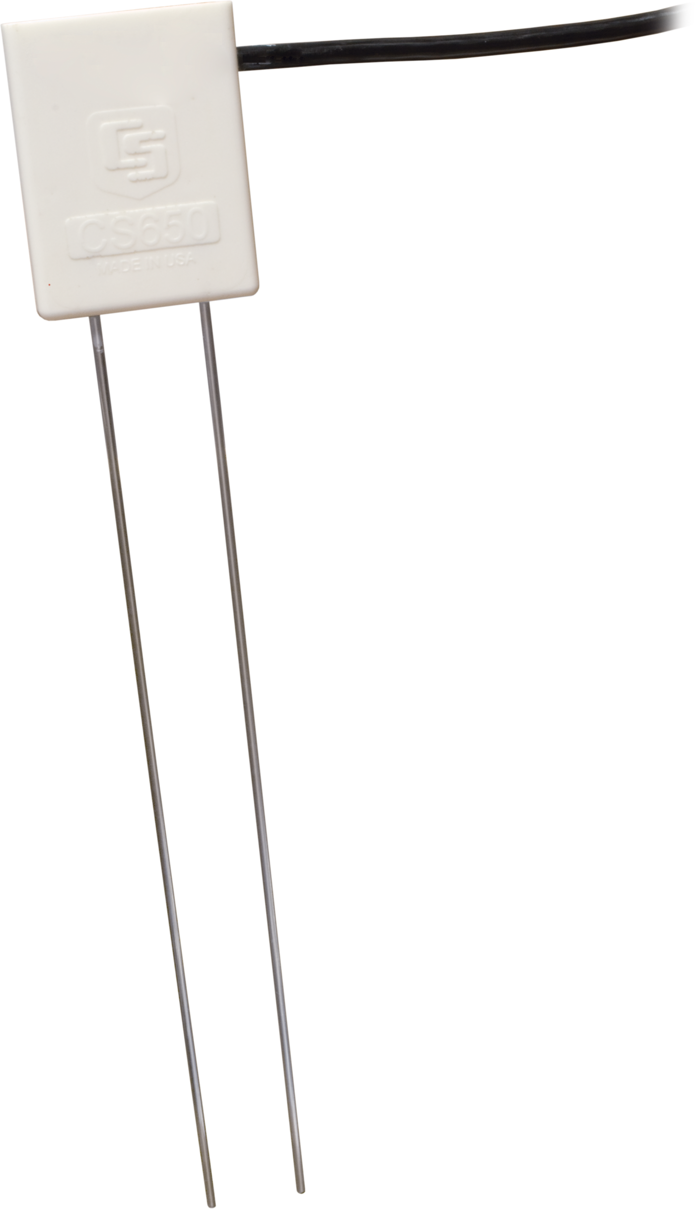
The CS650-LC is a multiparameter smart sensor that uses innovative techniques to monitor soil volumetric-water content, bulk electrical conductivity, and temperature. This sensor is used with the ET107 Weather Station.
Note: The cable connector for this sensor is suitable for use with an ET107 station. For other cable termination options, use the CS650 sensor instead.
Technical Description
The CS650-LC consists of two 30-cm-long stainless steel rods connected to a printed circuit board. The circuit board is encapsulated in epoxy and a shielded cable is attached to the circuit board for data logger connection.
The CS650-LC measures propagation time, signal attenuation, and temperature. Dielectric permittivity, volumetric water content, and bulk electrical conductivity are then derived from these raw values.
Measured signal attenuation is used to correct for the loss effect on reflection detection and thus propagation time measurement. This loss-effect correction allows accurate water content measurements in soils with bulk EC ≤3 dS m-1 without performing a soil specific calibration.
Soil bulk electrical conductivity is also calculated from the attenuation measurement. A thermistor in thermal contact with a probe rod near the epoxy surface measures temperature. Horizontal installation of the sensor provides accurate soil temperature measurement at the same depth as the water content. Temperature measurement in other orientations will be that of the region near the rod entrance into the epoxy body.
Specifications
- Sensing Volume
- 7800 cm3
(~7.5 cm radius around each probe rod and 4.5 cm beyond the end of the rods)
- Electromagnetic
- CE compliant
Meets EN61326 requirements for protection against electrostatic discharge and surge. - Operational Temperature
- -10° to +70°C
- Sensor Output
- SDI-12; serial RS-232
- Measurement Time
- 3 ms to measure; 600 ms to complete SDI-12 command
- Power Supply Requirements
- 6 to 18 Vdc
(Must be able to supply 45 mA @ 12 Vdc.)
- Maximum Cable Length
- 610 m
(2000 ft) combined length for up to 10 sensors connected to the same data logger control port
- Rod Spacing
- 32 mm
(1.3 in.)
- Ingress Protection Rating
- IP68
- Rod Diameter
- 3.2 mm
(0.13 in.)
- Rod Length
- 300 mm
(11.8 in.)
- Probe Head Dimensions
- 85 x 63 x 18 mm
(3.3 x 2.5 x 0.7 in.)
- Cable Weight
- 35 g per m
(0.38 oz per ft)
- Probe Weight
- 280 g
(9.9 oz) without cable
Current Drain
- Active (3 ms)
- 45 mA typical
(@ 12 Vdc)
80 mA(@ 6 Vdc)
35 mA(@ 18 Vdc)
- Quiescent
- 135 µA typical
(@ 12 Vdc)
Electrical Conductivity
- Range for Solution EC
- 0 to 3 dS/m
- Range for Bulk EC
- 0 to 3 dS/m
- Accuracy
- ±(5% of reading + 0.05 dS/m)
- Precision
- 0.5% of BEC
Relative Dielectric Permittivity
- Range
- 1 to 81
- Accuracy
- ±(2% of reading + 0.6)
for solution EC ≤ 3 dS/m (for 1 to 40 range)
±1.4(for solution EC ≤1.0 dS/m) for 40 to 81 range
- Precision
- < 0.02
Volumetric Water Content
- -NOTE-
- Using Topp Equation (m3/m3)
- Range
- 5% to 50%
- Accuracy
- ±3% VWC
(typical in mineral soils, where solution EC ≤ 3 dS/m)
- Precision
- < 0.05%
Soil Temperature
- Range
- -10° to +70°C
- Accuracy
- ±0.5°C
(for probe body buried in soil)
- Precision
- ±0.02°C
Similar Products
(1)
Compatibility
RF Considerations
External RF Sources
External RF sources can affect the probe’s operation. Therefore, the probe should be located away from significant sources of RF such as ac power lines and motors.
Interprobe Interference
Multiple CS650-LC probes can be installed within 4 inches of each other when using the standard data logger SDI-12 “M” command. The SDI-12 “M” command allows only one probe to be enabled at a time.
Installation Tools
14384 Pilot Tool
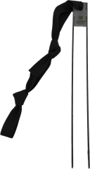
The 14384 Pilot Tool has rods with similar diameters and the same spacing as the probe. The tool can be driven into the soil using force levels that might damage the probe. After removing the 14384, the probe is inserted into the established holes.
14383 Installation Tool
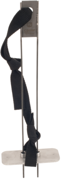
The 14383 Installation Tool can be used to help maintain the proper spacing and parallel orientation of rods during insertion. Use of the 14383 may reduce measurement errors by minimizing soil disturbance.
Related Resources
Documents
- Brochure
ET107 Evapotranspiration Station
June 2017
View Document - Manual
ET107 Evapotranspiration Monitoring Station
March 2021
View Document - Manual
CS650 and CS655 Product Manual (online)
July 2024
View Document - Manual
SDI-12 Terminal Bus Kit Getting Started Guide (online)
May 2026
View Document
Showing 4 of 7 results
See all DocumentsDownloads
Videos and Tutorials
SDI-12 Sensors | Transparent Mode
November 27, 2013 (7:06)
Communicating with an SDI-12 sensor
Watch
SDI-12 Sensors | Watch or Sniffer Mode
November 27, 2013 (3:20)
Watching communication between an SDI-12 sensor and a datalogger
Watch
Installing a Soil Moisture Reflectometer Sensor
June 30, 2025 (5:56)
Full procedure to bury a soil moisture reflectometer sensor
Watch