No physical contact necessary


Overview
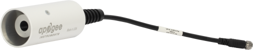
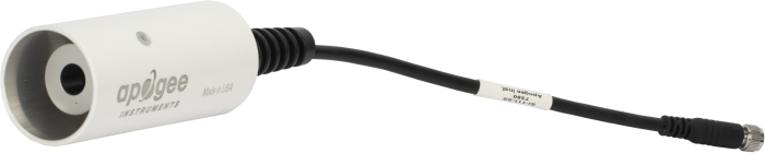
The SI-111SS, manufactured by Apogee, is a precision infrared radiometer that determines the surface temperature of an object without physical contact. It measures both the subject's surface temperature and the sensor-body temperature. A Campbell Scientific data logger uses these measurements to calculate the correct temperature of the subject.
This radiometer features an IP67-rated, marine-grade 316L connector that allows the user to easily swap sensors for recalibration or to replace damaged cables.
Read MoreBenefits and Features
- Compatible with most Campbell Scientific data loggers
- Measures surface temperature continuously in the field
- Provides road surface, plant canopy, soil surface, snow surface, and water surface temperature measurements
- Avoids influencing the temperature, providing more accurate measurements
- Ideal for providing spatial averages
- Rugged construction—two temperature probes housed in an aluminum body with a germanium window
Images
Detailed Description
The SI-111SS consists of a thermopile, which measures surface temperature, and a thermistor, which measures sensor body temperature. The two temperature sensors are housed in a rugged aluminum body that contains a germanium window.
Both the thermopile and the thermistor output a millivolt signal that most of our data loggers can measure. The data logger uses the Stefan-Boltzman equation to correct for the effect of sensor body temperature on the target temperature. The corrected readings yield an absolute accuracy of ±0.2°C from -10° to +65°C.
Field of View (FOV)
The SI-111SS has a 22-degree half-angle field-of-view (FOV). The FOV is reported as the half-angle of the apex of the cone formed by the target (cone base) and the detector (cone apex). The target is a circle from which 98% of the radiation viewed by the detector is being emitted.
Specifications
| Sensor | Thermopile and thermistor |
| Input Power | 2.5 V excitation (for thermistor) |
| Response Time | < 1 s (to changes in target temperature) |
| Target Temperature Output Signal | 60 μV per °C difference from sensor body |
| Body Temperature Output Signal | 0 to 2500 mV |
| Optics | Germanium lens |
| Wavelength Range | 8 to 14 μm (corresponds to atmospheric window) |
| Field of View (FOV) | 22° half angle |
| Operating Temperature Range | -55° to +80°C |
| Operating Relative Humidity Range | 0 to 100% RH |
| Cable Description | 4.5 m (14.76 ft) twisted, shielded 4-conductor wire with Santoprene casing, ending in pigtails |
| Absolute Accuracy |
|
| Uniformity |
|
| Repeatability |
|
| Diameter | 2.3 cm (0.9 in.) |
| Length | 6 cm (2.4 in.) |
| Weight | 190 g (6.7 oz) |
Compatibility
Note: The following shows notable compatibility information. It is not a comprehensive list of all compatible or incompatible products.
Data Loggers
| Product | Compatible | Note |
|---|---|---|
| CR1000 (retired) | ||
| CR300 | ||
| CR3000 (retired) | ||
| CR310 | ||
| CR350 | ||
| CR6 | ||
| CR800 (retired) | ||
| CR850 (retired) |
Additional Compatibility Information
Mounting
The SI-111SS is often fastened to a CM200-series crossarm, a tripod or tower mast, or a user-supplied pole using a CM230, CM230XL, or CM220 mount. The CM230 and CM230XL are adjustable inclination mounts that allow the SI-111SS to be mounted perpendicular to the target surface when the target surface is on an incline. The CM230XL is similar to the CM230, but the CM230XL places the SI-111SS further from the pole or crossarm. The SI-111 may also be attached directly to a user-supplied camera tripod.
Documents
Frequently Asked Questions
Number of FAQs related to SI-111SS: 8
Expand AllCollapse All
-
No. The SI-111SSCBL is used with the SI-111SS.
-
There are two accuracy specifications listed for the SI-111SS:
- One for when the difference in the target and sensor body temperatures is less than 20°C (more accurate)
- One for when the difference in the target and sensor body temperatures is greater than 20°C (less accurate)
Using a radiation shield with the sensor helps keep the sensor body temperature in close approximation to the ambient air temperature. Ultimately, the need to protect the sensor from short-wave radiation is dependent on what is being measured and under what conditions. For example, Campbell Scientific recommends using a radiation shield for canopy measurements.
-
As a general recommendation, recalibration should be done every two years.
-
The SI-111SS can be used to measure a wide variety of surfaces, including water and snow. When measuring objects with low emissivity, however, it is particularly important to apply corrections to the measurement.
-
The information included on a calibration sheet differs with each sensor. For some sensors, the sheet contains coefficients necessary to program a data logger. For other sensors, the calibration sheet is a pass/fail report.
-
The window in the Apogee infrared sensor is inset and protected, but it can become partially blocked in three ways:
- Spiders can make a nest in the entrance. Campbell Scientific recommends using a cotton swab to apply a spider repellent around the entrance to the aperture. Do not apply the repellent, however, to the sensor window itself.
- Calcium deposits can accumulate on the window if irrigation water sprays up on the head. These deposits typically leave a thin white film on the surface, which can be removed with a diluted acid, such as vinegar. Calcium deposits cannot be removed with solvents such as alcohol or acetone.
- In windy environments, dust and dirt can be deposited in the aperture. The aperture can be cleaned with deionized water, rubbing alcohol, or in extreme cases, acetone.
Clean the inner threads and sensor window using a cotton swab dipped in the appropriate solvent. For additional cleaning information, see the Maintenance section of the instruction manual.
-
This depends on the information contained in the calibration sheet:
- If the calibration sheet contains coefficient information, Campbell Scientific keeps a copy, and a replacement copy can be requested.
- If the calibration sheet does not contain coefficients, Campbell Scientific does not keep a copy. It may be possible to contact the original manufacturer for a replacement copy.
-
Because of the loss of IR radiation, nearly all thermopile instruments typically have a negative offset. This offset is most easily visible at night-time, when a small negative value is read instead of zero. This same offset is present during the daytime, but it is not as visible because of the large solar signal.
Another common issue involves leveling an instrument. Leveling a thermopile instrument can cause errors in the direct beam component because the cosine response is not correct. These errors are more notable when the sun is close to the horizon because the angle is so shallow.
Privacy Policy Update
We've updated our privacy policy. Learn More
Cookie Consent
Update your cookie preferences. Update Cookie Preferences