
Product Line
| Sensor Type | Output | Orifice Diameter | Rainfall per Tip | Operating Temperature Range | Measurement Uncertainty | |
|---|---|---|---|---|---|---|
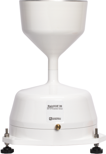
RainVue 20
|
Tipping bucket with magnetic reed switch | SDI-12 version 1.4 | 20.0 cm (7.87 in.) | — |
|
|
RainVue 10
|
Tipping bucket with magnetic reed switch | SDI-12 version 1.4 | 20.0 cm (7.87 in.) | — |
|
|
TE525-L
|
Tipping bucket with magnetic reed switch | — | 15.4 cm (6.06 in.) | 0.254 mm (0.01 in.) | 0° to 50°C | 1.0% up to 50 mm/h (2 in./h) |
Other Products
| Sensor Type | Output | Orifice Diameter | Rainfall per Tip | Operating Temperature Range | Measurement Uncertainty | |
|---|---|---|---|---|---|---|
TE525WS-L
|
Tipping bucket with magnetic reed switch | — | 20.3 cm (8 in.) | 0.254 mm (0.01 in.) | 0° to 50°C | 1.0% up to 50 mm/h (2 in./h) |
TE525MM-L
|
Tipping bucket with magnetic reed switch | — | 24.5 cm (9.66 in.) | 0.1 mm (0.004 in.) | 0° to 50°C | 1.0% up to 50 mm/h (2 in./h) |
CS700-L
|
Tipping bucket with siphon and dual reed switch | — | 20 cm (7.9 in.) | 0.254 mm (0.01 in.) | 0° to 70°C |
|
TB4-L
|
Tipping bucket with siphon and dual reed switch | — | 20 cm (7.9 in.) | 0.254 mm (0.01 in.) | 0° to 70°C |
|
TB4MM-L
|
Tipping bucket with siphon and dual reed switch | — | 20 cm (7.9 in.) | 0.2 mm (0.008 in.) | 0° to 70°C |
|
CS700H-L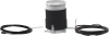
|
Tipping bucket with siphon and dual reed switch | SDI-12 | 20 cm (7.9 in.) | 0.01 in. (0.254 mm) |
|
|
52202-L
|
Tipping bucket with magnetic reed switch (normally open) | — | 16 cm (6.3 in.) | 0.1 mm (0.004 in.) | -20° to +50°C (heated) |
|
Retired Products


 to understand water loss from a native or a managed ecosystem is easier than it looks, but you have to know what you’re doing. If you can’t spend the time or money on a full eddy-covariance system, you’ll have to be satisfied with making some assumptions using equations such as Penman-Monteith.<br /><br />
Like any model, the accuracy of the output depends on the quality of the inputs, but do you know what measurements are critical for success? Plus, as your instrumentation gets more inaccurate, the errors get larger. If you’re not careful, you can end up with no idea what’s happening to the water in your system.<br /><br />
In this recorded webinar, Campbell Scientific scientist, Dr. Dirk V. Baker, and METER Group scientist, Dr. Colin Campbell, team up to discuss fundamentals, assumptions, required measurements, common pitfalls, accuracy, uncertainty, and much more.")
Documents
Brochures
Frequently Asked Questions
Number of FAQs related to Precipitation Sensors: 11
Expand AllCollapse All
-
Nixalite offers a variety of bird control products, including an architectural bird control wire that consists of stainless-steel needles coming out of a flexible metal band. Strap a strip of this wire around the funnel using a pipe clamp so that the needles extend up beyond the funnel.
-
The 260-953 Alter-type rain gage wind screen consists of 32 heavy metal leaves that hang freely and swing as the wind moves past them. The swinging leaves act as a wind damper and help minimize the effect of wind on the rain measurements without adding additional turbulence.
-
The most common errors are either that the rain gage appears to have drifted out of calibration or that the tips are not being correctly recorded by the data logger.
-
Sometimes, an old cable can be replaced with a new, shorter cable.
Sometimes, an existing cable can be shortened by cutting the ends off. However, there are a few issues that could be encountered when doing this:
- Some sensors have bridge completion resistors at the pigtail end.
- Some sensors are calibrated to length.
- Sometimes the color in the insulation may not be the same as that visible at the pigtail end.
Because of the potential issues, do not cut the ends off any sensor cable without first contacting Campbell Scientific to discuss the sensor in detail.
-
Most Campbell Scientific sensors are available as an –L, which indicates a user-specified cable length. If a sensor is listed as an –LX model (where “X” is some other character), that sensor’s cable has a user-specified length, but it terminates with a specific connector for a unique system:
- An –LC model has a user-specified cable length for connection to an ET107, CS110, or retired Metdata1.
- An –LQ model has a user-specified cable length for connection to a RAWS-P weather station.
If a sensor does not have an –L or other –LX designation after the main model number, the sensor has a set cable length. The cable length is listed at the end of the Description field in the product’s Ordering information. For example, the 034B-ET model has a description of “Met One Wind Set for ET Station, 67 inch Cable.” Products with a set cable length terminate, as a default, with pigtails.
If a cable terminates with a special connector for a unique system, the end of the model number designates which system. For example, the 034B-ET model designates the sensor as a 034B for an ET107 system.
- –ET models terminate with the connector for an ET107 weather station.
- –ETM models terminate with the connector for an ET107 weather station, but they also include a special system mounting, which is often convenient when purchasing a replacement part.
- –QD models terminate with the connector for a RAWS-F Quick Deployment Station.
- –PW models terminate with the connector for a PWENC or pre-wired system.
-
Not every sensor has different cable termination options. The options available for a particular sensor can be checked by looking in two places in the Ordering information area of the sensor product page:
- Model number
- Cable Termination Options list
If a sensor is offered in an –ET, –ETM, –LC, –LQ, or –QD version, that option’s availability is reflected in the sensor model number. For example, the 034B is offered as the 034B-ET, 034B-ETM, 034B-LC, 034B-LQ, and 034B-QD.
All of the other cable termination options, if available, are listed on the Ordering information area of the sensor product page under “Cable Termination Options.” For example, the 034B-L Wind Set is offered with the –CWS, –PT, and –PW options, as shown in the Ordering information area of the 034B-L product page.
Note: As newer products are added to our inventory, typically, we will list multiple cable termination options under a single sensor model rather than creating multiple model numbers. For example, the HC2S3-L has a –C cable termination option for connecting it to a CS110 instead of offering an HC2S3-LC model.
-
When a rain gage is out of calibration, it is usually because of the buildup of dirt and grime on the internal surfaces of the tipping bucket mechanism. Cleaning the internal surfaces usually brings the rain gage back into calibration. It is also possible that a rain gage is out of calibration because it is no longer level.
To minimize the possible occurrence of calibration errors, perform routine cleaning and maintenance of the rain gage at least once every three months. The environmental conditions at a particular site may require a facility to perform cleaning, leveling, and maintenance on a much more frequent schedule.
-
Whenever possible, purchase a sensor with the desired cable length. Some sensors have a user-specified cable length, whereas other sensors have a set cable length.
Sometimes, an old cable can be replaced with a new, longer cable.
Generally, additional cable cannot be spliced onto the existing cable because:
- Some sensor cables have bridge completion resistors at the pigtail end
- Some sensors are calibrated based on cable length
- Sometimes the color in the insulation is not the same as that visible at the pigtail end
- It is possible to introduce errors or malfunctions depending on the integrity of the splice
Splicing cable together increases the likelihood that water may enter the cable and cause shorting, corrosion, and some other potential issues, which in turn can cause measurement issues.
Because of the potential issues, do not splice any sensor cable without first contacting Campbell Scientific to discuss the sensor in detail.
-
Not every sensor comes with a calibration sheet. If a calibration sheet is included, it is listed in the “Ships With” section of the sensor’s product web page or it is specified when ordered.
-
Many Campbell Scientific sensors are available with different cable termination options. These options include the following:
- The –PT (–PT w/Tinned Wires) option is the default option and does not display on the product line as the other options do. The cable terminates in pigtails that connect directly to a data logger.
- In the –C (–C w/ET/CS110 Connector) option, the cable terminates in a connector that attaches to a CS110 Electric Field Meter or an ET-series weather station.
- In the –CWS (–CWS w/CWS900 Connector) option, the cable terminates in a connector that attaches to a CWS900-series interface. Connection to a CWS900-series interface allows the sensor to be used in a wireless sensor network.
- In the –PW (–PW w/Pre-Wire Connector) option, the cable terminates in a connector that attaches to a prewired enclosure.
- In the –RQ (–RQ w/RAWS Connector) option, the cable terminates in a connector that attaches to a RAWS-P Permanent Remote Automated Weather Station.
Note: The availability of cable termination options varies by sensor. For example, sensors may have none, two, or several options to choose from. If a desired option is not listed for a specific sensor, contact Campbell Scientific for assistance.
Privacy Policy Update
We've updated our privacy policy. Learn More
Cookie Consent
Update your cookie preferences. Update Cookie Preferences