
PTFE-coated absorbers instead of fragile dome


Overview
The NR-LITE2, manufactured by Kipp & Zonen and cabled for use with Campbell Scientific data loggers, is a rugged net radiometer that measures the energy balance between incoming short-wave and long-wave infrared radiation relative to surface-reflected short-wave and outgoing long-wave infrared radiation. It is directly connected to a Campbell Scientific data logger and is widely used in agriculture and hydrology applications.
Read MoreBenefits and Features
- Compatible with most Campbell Scientific data loggers
- Integrated bubble level ensures proper installation
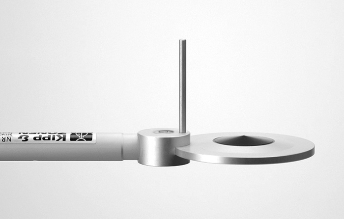
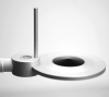
- Includes rod that deters birds from roosting on the radiometer
- PTFE-coated absorbers are weather resistant without using a fragile plastic dome
Images


Detailed Description
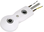
The NR-LITE2 includes two black conical absorbers—one facing upward and the other facing downward. The absorbers are coated in PTFE, making them resistant to weather without using a fragile plastic dome. Both absorbers are calibrated to an identical sensitivity coefficient.
The NR-LITE2 has a bubble level to ensure proper installation and a rod that deters birds from roosting on the sensor. It produces a millivolt signal that is measured directly by a Campbell Scientific data logger.
Specifications
| Sensor | Two black conical absorbers—one facing upward and the other facing downward |
| Measurement Description | Measures incoming and outgoing short-wave and long-wave radiation |
| Spectral Range | 0.2 to 100 µm |
| Response Time | < 20 s (nominal) |
| Sensitivity | 10 µV W-1 m2 (nominal) |
| Output Range | ±25 mV |
| Measurement Range | ±2000 W m-2 |
| Operating Temperature Range | -40° to +80°C |
| Sensor Diameter | 8.0 cm (3.1 in.) |
| Support Arm Diameter | 1.6 cm (0.6 in.) |
| Support Arm Length | 80 cm (31.5 in.) |
| Sensor Weight | 200 g (7.0 oz) |
| Support Arm Weight | 635 g (23 oz) |
Compatibility
Note: The following shows notable compatibility information. It is not a comprehensive list of all compatible or incompatible products.
Data Loggers
| Product | Compatible | Note |
|---|---|---|
| CR1000 (retired) | ||
| CR1000X | ||
| CR300 | ||
| CR3000 (retired) | ||
| CR310 | ||
| CR350 | ||
| CR6 | ||
| CR800 (retired) | ||
| CR850 (retired) |
Additional Compatibility Information
Mounting
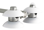
To avoid shading/reflections and to promote spatial averaging, the NR-LITE2 should be mounted at least 1.5 m above the ground or crop canopy and away from all obstructions or reflective surfaces that might adversely affect the measurement. Campbell Scientific recommends mounting the NR-LITE2 to a separate vertical pipe at least 25 ft away from other mounting structures. The 26120 Net Radiation Sensor Mounting Kit is used to mount the NR-LITE2 to a vertical pole or a horizontal crossarm, such as the CM202, CM203, CM204, or CM206.
Documents
Brochures
Manuals
Frequently Asked Questions
Number of FAQs related to NR-LITE2-L: 12
Expand AllCollapse All
-
Yes, as long as the correct AWG for the cable is used. In addition, the extension point should be water tight. The total cable length should not exceed 100 ft because signal dissipation can become too great along the cable.
-
The calibration of the NR-LITE2-L is carried out at zero wind speed. At any other wind speed, the sensitivity will decrease. It has been shown that this decrease in sensitivity is less than 1% of reading per m/s wind speed, and the effect is essentially independent of the radiation level. More information about this can be found in the "Sensitivity to Wind Speed" subsection in the "Overview" section of the instruction manual.
-
The net radiation measurement must be scaled to give total megajoules per square meter (MJ/m2) received during the period between calling the output table with the ETsz() instruction in it. (This is normally the scan interval.) If the sensor is scaled to output flux, the value needs to be converted to megajoules. For example, if the output flux unit is W/m2, multiply the flux value by the scan interval (in seconds) and by 10-6 to convert the value to megajoules (that is, MJ = W x scan x 10-6).
-
Albedo is the fraction of solar energy (short-wave radiation) reflected from the Earth back into space. It is a measure of the reflectivity of the surface of the earth. Because this sensor does not produce separate components of the long-wave and short-wave radiation, it is impossible to properly calculate the albedo.
-
As of June 2013, all of our current and retired net radiation sensors can be mounted using this kit. These include:
- Current sensors: CNR4-L, NR-LITE2-L, and NR01-L
- Retired sensors: CNR1, CNR1-L, CNR2-L, NR-LITE-L, and Q7.1-L
-
Mount the net radiometer so that no shadow will be cast on it at any time of day from obstructions such as trees, buildings, the mast, or the structure on which it is mounted.
Campbell Scientific recommends installing a net radiometer in an open area, away from the main weather station structure on a separate vertical mast. If it is necessary to install this sensor on the main tall tower (30 ft or taller), the sensor should be installed at the top of the tower. In the northern hemisphere, the sensor should be facing south. In the southern hemisphere, the sensor should be facing north. If the tower uses a solar power system (that is, solar panels), ensure that the solar panels are installed away from the main tower.
-
The information included on a calibration sheet differs with each sensor. For some sensors, the sheet contains coefficients necessary to program a data logger. For other sensors, the calibration sheet is a pass/fail report.
-
Most Campbell Scientific sensors are available as an –L, which indicates a user-specified cable length. If a sensor is listed as an –LX model (where “X” is some other character), that sensor’s cable has a user-specified length, but it terminates with a specific connector for a unique system:
- An –LC model has a user-specified cable length for connection to an ET107, CS110, or retired Metdata1.
- An –LQ model has a user-specified cable length for connection to a RAWS-P weather station.
If a sensor does not have an –L or other –LX designation after the main model number, the sensor has a set cable length. The cable length is listed at the end of the Description field in the product’s Ordering information. For example, the 034B-ET model has a description of “Met One Wind Set for ET Station, 67 inch Cable.” Products with a set cable length terminate, as a default, with pigtails.
If a cable terminates with a special connector for a unique system, the end of the model number designates which system. For example, the 034B-ET model designates the sensor as a 034B for an ET107 system.
- –ET models terminate with the connector for an ET107 weather station.
- –ETM models terminate with the connector for an ET107 weather station, but they also include a special system mounting, which is often convenient when purchasing a replacement part.
- –QD models terminate with the connector for a RAWS-F Quick Deployment Station.
- –PW models terminate with the connector for a PWENC or pre-wired system.
-
Not every sensor has different cable termination options. The options available for a particular sensor can be checked by looking in two places in the Ordering information area of the sensor product page:
- Model number
- Cable Termination Options list
If a sensor is offered in an –ET, –ETM, –LC, –LQ, or –QD version, that option’s availability is reflected in the sensor model number. For example, the 034B is offered as the 034B-ET, 034B-ETM, 034B-LC, 034B-LQ, and 034B-QD.
All of the other cable termination options, if available, are listed on the Ordering information area of the sensor product page under “Cable Termination Options.” For example, the 034B-L Wind Set is offered with the –CWS, –PT, and –PW options, as shown in the Ordering information area of the 034B-L product page.
Note: As newer products are added to our inventory, typically, we will list multiple cable termination options under a single sensor model rather than creating multiple model numbers. For example, the HC2S3-L has a –C cable termination option for connecting it to a CS110 instead of offering an HC2S3-LC model.
-
This depends on the information contained in the calibration sheet:
- If the calibration sheet contains coefficient information, Campbell Scientific keeps a copy, and a replacement copy can be requested.
- If the calibration sheet does not contain coefficients, Campbell Scientific does not keep a copy. It may be possible to contact the original manufacturer for a replacement copy.
Articles and Press Releases
Blog Articles
-
6 Tips to Protect Your Weather Station from Birds

05-25-2016 Author: Robin Deissinger
Privacy Policy Update
We've updated our privacy policy. Learn More
Cookie Consent
Update your cookie preferences. Update Cookie Preferences